You can order the whole kit and get great savings or even buy the parts individually, as needed.
Gearing: For same top end and tons more low end power, use the stock gearing. If you want more top speed to utilize the true power of the 21 class engine, try experimenting with high speed gears such as the 22 Tooth Clutch Bell and/or the 70 Tooth Spur Gear.
Important: Identify all parts and how they are positioned before starting installation. This will help ensure you assemble the kit properly the first time.
 T-Maxx .21 Conversion Directions
This is a composite of both instruction sets that are included with the kit.
Your T-Maxx must be partially disassembled before you install any of the conversion parts on your T-Maxx. With the wheels removed from the truck, it will allow you to move parts of the truck around in a much easier manner. Remember to save all of your screws and note where they came from. Many of the screws that you remove from your chassis will be used later to replace many of the components that you remove.
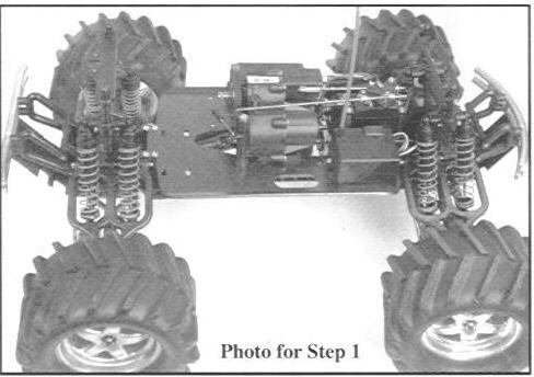
Step 1
Remove the old engine and exhaust from your truck by removing the screws that hold on the engine mount to the old chassis. Additionally, remove the EZ-start system and wiring that is attached to the engine. The fuel tank can also be removed at this point.
 Step 2
Remove all of the radio equipment and servos from the old chassis. Only remove the bottom screws from the chassis allowing the radio system to be removed as one unit. By loosening the set screw in the brake lever, the throttle servo can be removed without any prolem. Note -- T-Maxxes using the 2.5 engine will also need to remove the throttle bell crank. Make a note of what screws were removed from the parts that were removed.
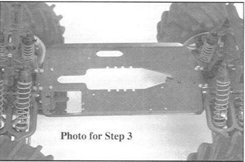
Step 3
Remove the transmission and chassis braces from the truck (old chassis) by removing the eight (8) screws that hold on the transmission, and the eight (8) screws that attach the chassis braces to the front and rear skid plates. At this point, you should be left with a bare chassis with only the front and rear ends attached. Once the transmission is out, remove the four (4) output joints that attatched the transmission to the front and rear differentials by removing the set screw yoke pins. Note -- The two output joints that were removed from the differentials have a larger inner diameter that the two output joints coming off of the transmission.
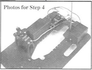
 Step 4
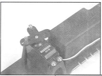
Install the radio system to the new chassis out of the conversion kit. Use the original screws that were taken from the original chassis when the radio system was removed. Most of the radio system is installed back to its original position except for the throttle servo. When installing the throttle, we recommend its placement to be next to the battery box. The excess servo lead that is in the receiver box will have to be pulled out in order for the throttle servo to reach. While the throttle servo is out of the truck, we recommend moving the brake connector to the middle hole on the servo horn in order to properly move the brake lever. In this location, the throttle servo can actuate almost any .21 size engine with a sliding carburetor. Next, install the tuned pipe mount on to the chassis in the 4mm hole next to the exhaust hole in the chassis using the supplied 4mm screw and countersunk washer. Leave the tuned pipe mount slightly loose.
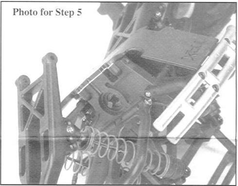
 Step 5
Remove the front and rear assemblies from the stock chassis by unscrewing the eight (8) countersunk screws that hold them, and the two (2) machine screws that tighten in to the steering assembly. With the assemblies out, the stock drive axles will be easier to remove. By removing the screws that attach the lower suspension arms to the bulkheads you will be able to remove the differential set screw yoke pins and differential outputs, the plastic sliders and the wheel axles.
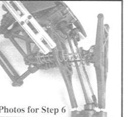
 Step 6
Install the center universals to the appropriate gear box using the set screw yoke pin from the plastic output. Note -- The shorter center universal is for the front and the longer is for the rear. Next, take the four metal output joints that are packaged with the wheel universals and install them on to the differential output shafts using the set screw yoke pins that were installed in the plastic differential output joints. Next, slide the metal universals through the wheel hub so the universal bone will mate to the metal universal output joint. Replace the lower arm to its normal position and install the suspension arm screw back into the bulkhead securing the suspension arm in place. Once all four metal outputs and universals are installed, install the front and rear assemblies to the new chassis from the conversion which should already have the radio system installed. N ote -- Do not tighten the eight (8) countersunk screws to the chassis all the way. Leave some play so the transmission will be easier to install.
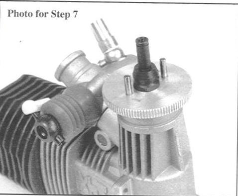
Step 7
Engine
Remove the clutch assembly from your stock engine and install it onto the new 21. This includes the clutch bell, bearings, clutch nut. These parts, exluding the clutch nut, will be used with the conversion. Note -- Depending on what engine you use with the XTM conversion, you may need to cut the crankshaft of your engine or use shims on the crankshaft in order for the clutch assembly to fit and align properly. Two clutch nuts are included with the conversion kit for use on engines with a regular shaft or those engines using an SG shaft. Use the provided clutch nut. While you have it apart, you may want to check for wear. This would be a great time to replace the clutch shoes if they look worn.
Install the original collet and flywheel on to your big block engine and secure it by tightening the appropriate clutch nut that is included with the conversion. Using a piston or crank lock tool can be helpful in this situation. Next, install the clutch shoes and clutch bell just as it was on your Traxxas engine. Note -- If an engine is being used with an SG shaft, you must secure the clutch assembly by using a 3mm screw and washer at the end of the crankshaft. Make sure your clutch bell spins freely and has no more than 1mm of play.
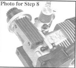
Step 8
Chassis Replacement
Install the new engine mounts onto the new chassis first.
When installing the engine mounts, use the screws that were supplied with engine mounts and not the original screws from the Traxxas engine. Place a split washer on each screw and place the four (4) screws through the engine mounts ot eh engine's crankcase. Thread the supplied locknuts on the screws just slightly. This will allow the engine mounts to slide on easily. Once the engine mounts are on the engine, tighten the screws just enough to hold the engine mounts in place. We will tighten the screws later.
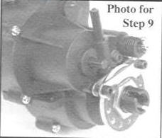
Step 9
With the brake disc and adapter on one of the metal transmission output joints that came with the center universals, install the outputs using the set screw yoke pins. Note -- If the stock brake disk adapter seems to fit loosely, use the brake disk adapter that is included in the conversion kit. The transmission is now ready to be installed in the conversion chassis. Carefully place the center universals into the transmission output joints as the transmission is lowered into the truck. Place the aluminum extended chassis braces that came with the conversion kit into position and begin to tighten the transmission with the eight (8) screws from the stoc chassis braces, but do not tighten them all the way. Begin to tighten the extended chassis braces to the skid plates using the eight (8) countersunk screws that came with the conversion kit. Note -- tighten the screws equally to make sure everything is aligned properly. Make sure all the chassis screws are tight at this point.
Step 10
Engine Position:
The engine must be positioned propery so that the gear mesh an the gear does not rub on the clutch bell.
Place the engine with the attached engine mounts on the chassis. Hold the engine mounts in place by screwing in the 5mm engine mount screws through the chassis and into the engine mounts. Leave the screws slightly loose so you may align the gear mesh properly. First adjust the front-to-back position with the engine mounting screws. Now the gear mesh must be adjusted. The motor mount screws on the bottom of the chassis control this (notice they are installed in the slotted holes). The gears should have some "play" or "backlash". If they are too tight, they cause excessive drag on the engine and premature gear wear. Too loose and they will fail. Use the Traxxas manual as a guide to set the mesh. Once you have achieved the proper gear mesh (a paper's width of play), tighten the eight (8) screws that hold the engine to the engine mounts and the engine mounts to the chassis.
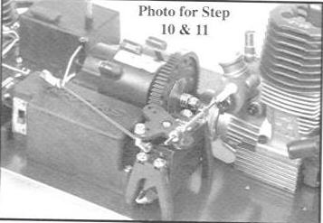
Step 11
Be careful when attaching the throttle linkages. The linkage wires from the conversion kit are used in conjunction with the spring and collars from the stock linkages. On the brake linkage (no threads), place a stopper at one end of the linkage. Slide a small piece of fuel line (3/8") on the brake linkage followed by a small flat washer from the original brake linkage. Slide the empty end of the brake linkage throught the brake lever and pass it through the eyelet on the bottom side of the throttle servo. Secure it with another stopper. Your brake linkage should activate the brake as the linkage moves towards the fuel tank. The throttle linkage is very similar. Tighten the ball cup from your engine on the threads of the throttle linkage. Place a stopper halfway down the throttle linkage followed by the spring that came installed on the stock linkage. Pass the empty end of the throttle linkage through the eyelet on the topside of the throttle horn. Secure it with another stopper. Press the ball cup on the carburetor ball and make sure the linkage moves towards the left side of the truck, the carburetor should open. As the throttle linkage moves towards the engine, the carburetor should close and the brake should activeate. Fine adjustments may be needed in order for the carburetor and brake to perform correctly. When adjusted properly, the brake will be applied just as idle on the carburetor is reached. Set this just as you would with your stock engine. The fuel tank can now be installed. Route the wires from the servo to the receiver box so that they do not interfere with the linkages.
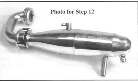
Step 12
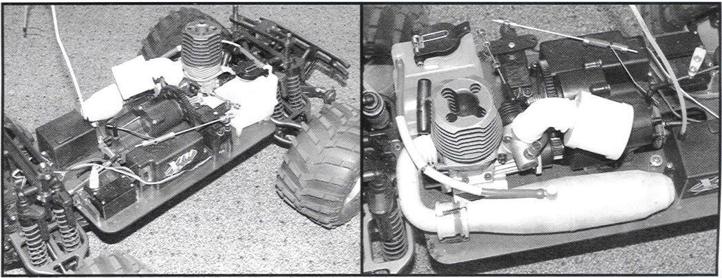
Place one of te enclosed gaskets that came with the header in the conversion kit on the tuned pipe. Slide the header over the gasket on the tumed pipe until it presses on all the way. Note -- Placing a drop of oil around the gasket will help the header slide on. Using a small pair of pliers, secure the header and tuned pipe together using the three (3) small springs.
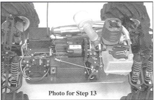
Step 13
Attach the header to the engine using the large exhaust spring from the conversion kit. Once secure, attach the tuned pipe mount with the supplied hanger wire that passes through the tuned pipe and tuned pipe mount. When the exhaust is aligned properly, the tuned pipe and tuned pipe mount can be secured in place with a 4mm set screw. Install the air filter from the conversion kit on the carburetor of your engine with the enclosed zip ties.
Step 14
Make sure the fuel line is attached from the lower part of the fuel tank to the carburetor, and from the tuned pipe to the upper part of the fuel tank. Install the heat protectors on the new line where the line passes by the head and exhaust. Attach the transmission servo's linkage back on the transmission and make sure the steering is secure.
Questions?
E-mail us

© 2004-2006 RcChopShop.com, Inc.


